
Short answer: A 16-pin OBD adapter harness should be bought from a verified wiring requirement, not from connector shape alone. The listed Tooluse product is an OBD adapter in a locked 3 x 16 AWG configuration, with one listed SKU and package data of 51 x 31 x 24 cm and 19 g. The product manufacturer does not specify a pinout, vehicle or ECU compatibility list, connector allocation, programming ability or software support. Compare the exact vehicle manual, ECU documentation and scan-tool instructions before connection, and follow the tool manufacturer's safe connection sequence rather than treating this adapter as a scanner or programmer.
Start with the adapter's documented identity
The product page describes a 3 x 16 AWG OBD Adapter and records one listed SKU. It also gives package data of 51 x 31 x 24 cm and 19 g. Those are the product facts available for this buying decision; they do not identify a particular vehicle, ECU, protocol, scan tool or software package.
The product manufacturer does not specify the pinout, connector gender, terminal allocation, working lead length, current rating, fuse arrangement or kit contents in the cited record. Treat every one of those fields as open until the manufacturer supplies a matching drawing or the vehicle and tool makers document the required route.
| Published | Manufacturer does not specify |
|---|---|
| 3 x 16 AWG configuration | Pin-by-pin routing |
| Single listed SKU | Vehicle, ECU or software coverage |
| Package data: 51 x 31 x 24 cm, 19 g | Finished lead length or electrical rating |
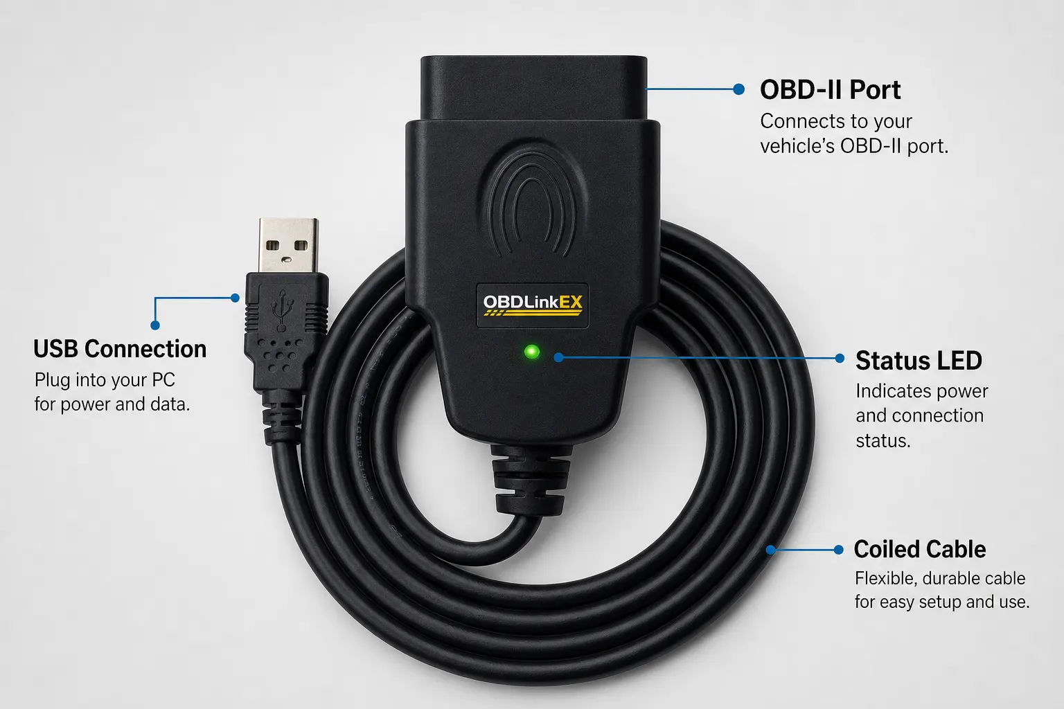
Match the harness to the exact vehicle job
A 16-pin connector can appear in different vehicle and conversion contexts. Your job may be a standard diagnostic connection, a modified loom, an ECU bench arrangement or a replacement for a damaged lead. Those are not interchangeable requirements. The product title cannot prove that the three listed conductors reach the pins your particular vehicle or ECU uses.
Use the vehicle maker's manual and the diagnostic tool maker's instructions as the controlling documents. If a required route, connector, protocol or power condition is missing from those documents or from the product record, write manufacturer does not specify and pause the purchase.
A cautious connection sequence
Autel's official scan-tool instructions say to switch the ignition off before connecting or disconnecting test equipment, then connect at the vehicle's 16-pin data link connector and follow the tool's own procedure. That is guidance for the cited Autel tool, not proof that this Tooluse adapter is compatible with it. Your vehicle and tool manuals remain the controlling instructions.
HSE's motor-vehicle repair guidance also places basic vehicle stability and safe working conditions before repair activity. An adapter does not make a vehicle safe to work on, and no connection procedure should bypass the vehicle maker's precautions.
- Identify the exact vehicle, ECU, diagnostic connector and tool model; record the relevant manual revisions.
- Obtain the adapter pinout and compare every required supply, earth and communication route before applying power.
- With ignition and equipment in the state required by the manufacturers, inspect the connector and make the connection without forcing it.
- Stop after any unexpected voltage, smell, heat, warning or communication result; disconnect only as the vehicle and tool manuals direct.
Limits and checks before buying
Do not describe the listed adapter as a scanner, ECU programmer, protocol converter, breakout box or software licence. The product manufacturer does not specify any of those capabilities, and the listing does not name a vehicle coverage set. A physically fitting connector is not evidence of electrical or software compatibility.
The product record also does not specify certification, insulation, environmental protection, service life, current capacity or safe use in a particular engine bay or bench setup. Buy only when the missing documents are supplied and match the exact vehicle and tool instructions.
Related guides and product details
Treat this as a narrowly documented wiring component: verify the exact pinout and tool procedure first, and do not buy on the promise of universal OBD coverage. Read OBD K-line Adapter Cable Pin 7: What to Verify for related guidance. Read OBD Wiring Harness 16 AWG: What to Verify Before Buying for related guidance. Review the documented specification on the 3 x 16 AWG OBD Adapter product page before ordering.
Sources and safety context
- Supports the listed configuration, single SKU and package data. Tooluse 3 x 16 AWG OBD Adapter product page.
- Supports the example manufacturer connection sequence and ignition-off warning for that Autel scan tool. Autel official scan-tool user manual.
- Supports basic vehicle stability and safe repair-work boundaries. HSE introduction to safe motor vehicle repair.