
Short answer: An OBD K-line adapter cable for pin 7 should be treated as a wiring verification task, not a guaranteed communication solution. Tooluse lists an OBD adapter in a locked 3 x 16 AWG configuration, but the product manufacturer does not specify a pin-by-pin diagram, vehicle coverage, ECU support, protocol support or programming function. Confirm that your exact vehicle or ECU documentation assigns the required signal to the intended connector position, then compare that route with the adapter drawing and the diagnostic tool manufacturer's instructions. If any link is missing, stop before applying power.
Pin 7 is a requirement to verify
The search phrase identifies a desired wiring route, not a published capability of the product. Tooluse documents an OBD adapter in the locked 3 x 16 AWG configuration, with a single listed SKU and package data of 51 x 31 x 24 cm and 19 g. It does not publish the pin map needed to prove a pin 7 connection.
The product manufacturer does not specify whether the listed conductors are assigned to K-line, power, earth or another function. Do not infer the route from the connector silhouette, wire gauge, a forum diagram or a similar-looking harness.
| Must be confirmed | Why the listing is not enough |
|---|---|
| Exact ECU and vehicle pinout | No vehicle or ECU family is named |
| Pin 7 route and terminal identity | No pin-by-pin diagram is published |
| Tool and protocol requirements | No software or programming support is specified |
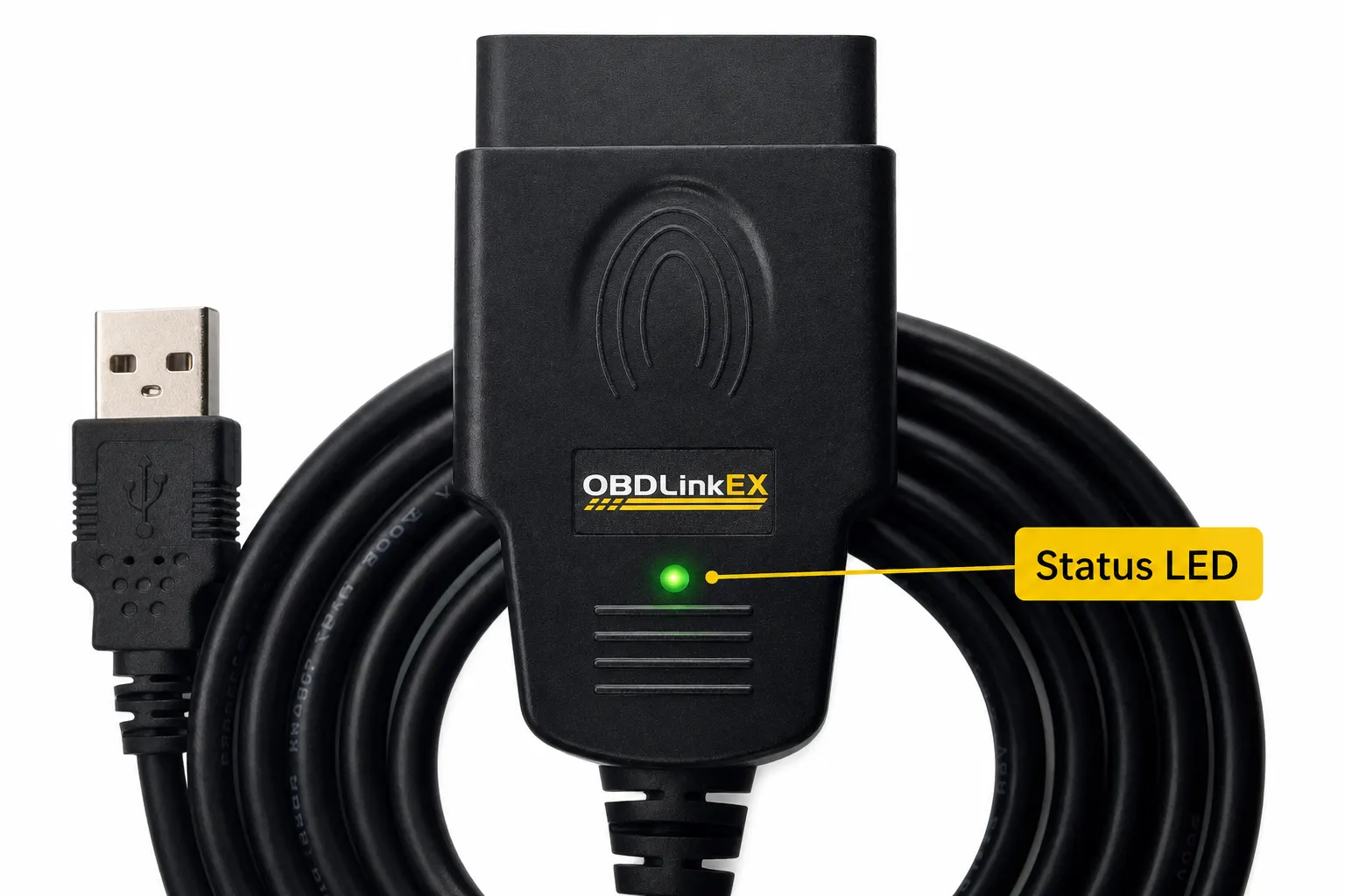
Build the pinout comparison
Use one comparison sheet for the exact ECU, vehicle connector and diagnostic tool. Record the required signal name, connector cavity, power and earth references, and any ignition or immobiliser condition stated by the relevant manufacturer. Keep the Tooluse product record beside that sheet, with unverified fields visibly marked.
A continuity check can confirm a conductor route after the wiring is documented, but it cannot prove protocol compatibility, correct vehicle software or safe programming conditions. The product manufacturer does not specify those capabilities.
- Write down the vehicle identification, ECU part number and diagnostic tool model from the relevant manuals.
- Mark the required pin 7, supply and earth paths on the exact diagrams; do not use a generic pinout.
- Obtain the adapter's pinout and connector details, then compare each conductor and terminal without applying power.
- Follow the vehicle and tool manufacturers' connection procedure and stop if the documents disagree.
Keep the cable separate from the tool
Autel's official manual is useful for one narrow safety example: turn the ignition off before connecting or disconnecting the scan tool, then use the tool's documented sequence. It does not establish that an unbranded or differently configured adapter works with an Autel device, a K-line ECU or any named software.
A harness or adapter does not automatically contain scanning electronics, a protocol converter, ECU software or programming voltage control. The product manufacturer does not specify those functions. Treat the adapter as a possible wiring component only until the complete system is documented.
Limits and stop conditions
Stop before connection if the adapter pin map is unavailable, the vehicle manual conflicts with the proposed route, the connector does not match without force, or the tool maker requires a condition not shown in the product record. A no-communication fault is not evidence that repeated reconnecting is safe.
HSE's motor-vehicle repair guidance includes precautions for stable vehicles and safe repair work. The cited product facts do not specify certification, current rating, insulation, environmental protection, service life or programming safety. Manufacturer does not specify means the claim stays unresolved.
Related guides and product details
For pin 7 work, buy only after the exact ECU and tool documents agree with a supplied adapter pinout; otherwise choose a harness whose routing is documented. Read OBD Wiring Harness 16 AWG: What to Verify Before Buying for related guidance. Read 16 Pin OBD Adapter Harness UK: What to Check Before You Buy for related guidance. Review the documented specification on the 3 x 16 AWG OBD Adapter product page before ordering.
Sources and safety context
- Supports the narrow product facts and the absence of published wiring support in the listing. Tooluse 3 x 16 AWG OBD Adapter product page.
- Supports the example ignition-off connection precaution for a named scan-tool manufacturer. Autel official scan-tool user manual.
- Supports the vehicle stability and repair-safety boundary. HSE introduction to safe motor vehicle repair.